As a quick refresher Power = Torque * Speed or in terms of units Watts = Newton*meter * 1/sec. Where Speed is in units of Radians/Sec
If we can get the torque and get the wheel speed out of the bike we have everything we need. In the very beginning of this project, in a worst case if I could only get the torque, I could always put a magnet on the rear wheel and measure the wheel speed directly to get that part.
Torque
I was very thankful the engineers at CycleOps who were nice enough to provide a diag nostics menu with the stock computer. This menu showed the raw output from the torque hub in counts. This was a life savor as it let me know when my decoding algorithm for the torque was correct. I spent many hours pushing on the crank arms with the torque adjuster as tight as it would go to test various decode algorithms. When I finally got it right see CycleOps Pro300 PT to ANTPlus, Details it turned out that 1 bit = 1 in*lb. So as you can see in the code
torque_Nm = (torque_in_lbs)*0.112984829;
I do the conversion in real time just to make the units easier to work with later (I really prefer to work in the metric system)
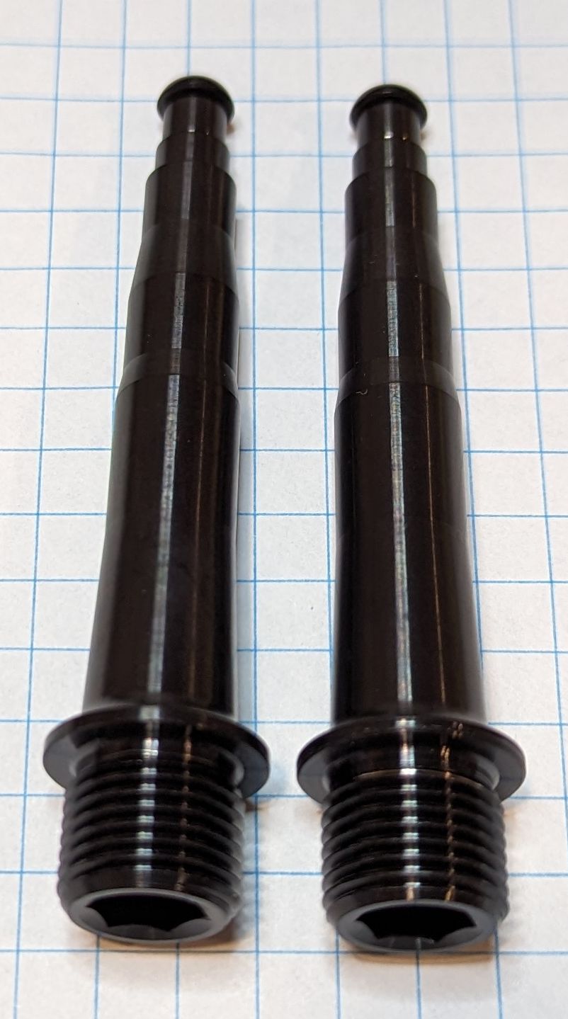
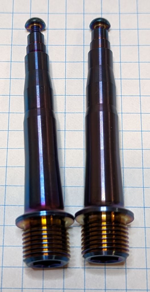
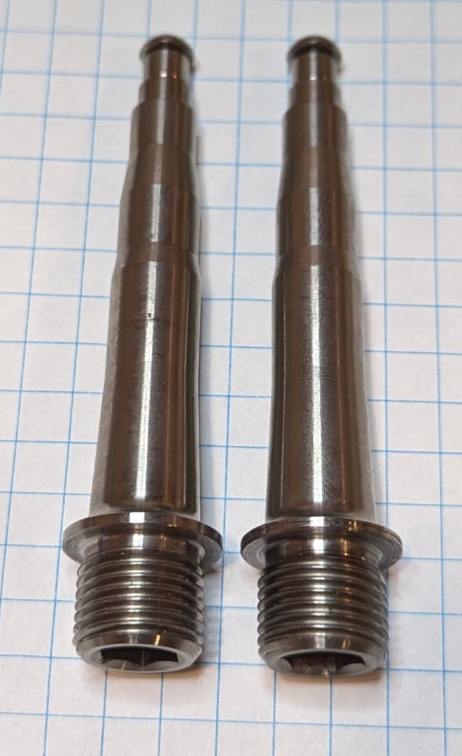
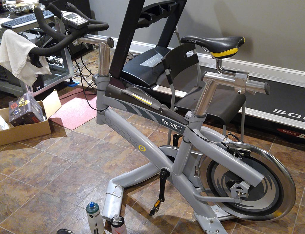
Being that this bike is close to 10 years old I didn’t want to just trust that it was still calibrated. The best place to hang weights was off the pedals. The crank arms are nicely labeled as being 170mm (I verified they are). Now I needed the tooth count of the crank arm chainring and the rear wheel chainring. I can’t really call it a cassette as this version of the bike behaves exactly like a fixed wheel, no coast at all. At first I thought this would be a problem but the spin bikes at my gym that I have been using for years are just like this and it’s not a problem at all.
Off comes the safety covers and with a little tape to mark my starting point. Several recounts later
Chainring
| Teeth |
Front
| 52 |
| Rear | 14 |
Gear Ratio = 3.714. Or to put it another way, torque applied to the crank arms will be reduced by 1/Gear Ratio = 0.26923
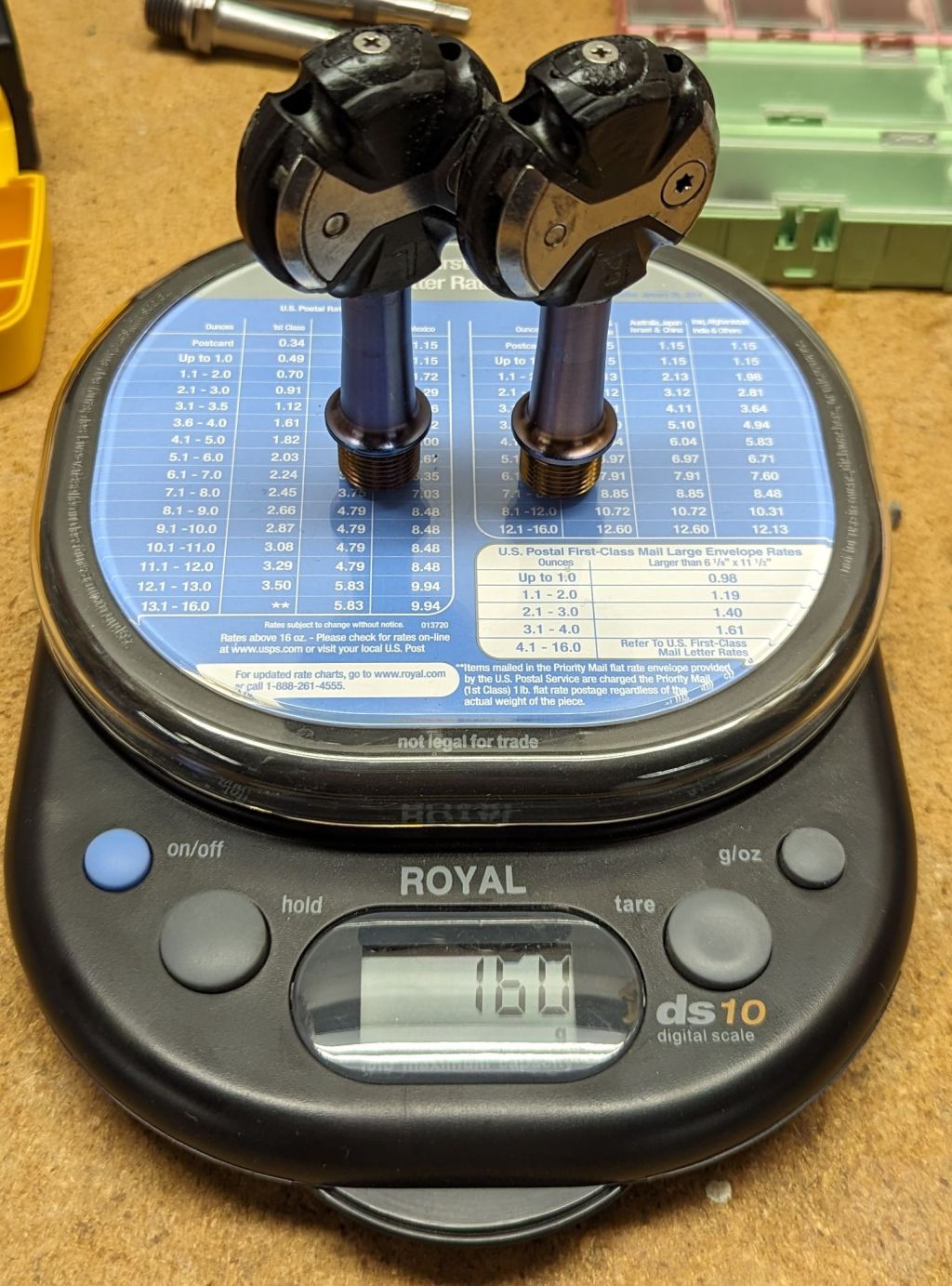
Grabbing some free weights and attaching some string made the rest of the process easy.
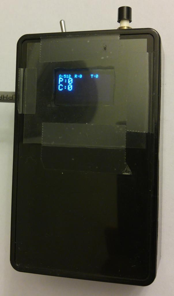
 Read the zero value
- Hang 15lbs, record the value
- Hang another 15lbs, record the value
- Balance 10lbs (because this is all I had to work with), record the value
I did this with the flywheel cold and after a hard 1 hour workout. I’ve read on other forums that this bike has a tendency to drift a small amount as the rear hub heats up. This is the oldest version of the bike with the torque tube welded into the flywheel. Newer version of this bike had the torque tube as a bolted in assembly. I can only guess that CycleOps recognized this issue and corrected it between these versions. For my purpose this is still fine as the slope of the output didn’t change at all, just the offset. I’ll deal with this by putting a zeroing button on my controller and after my warm-up, will zero the system. Some data for those interested
Applied Weight
(LB) | Raw Counts | Delta Counts | Torque on Rear Wheel (in*lb) | Cal Ratio
(in-lb/count) |
| 0 | 520 | 0 | 0 | |
| 15 | 548 | 28 | 27 | 0.965 |
| 30 | 573 | 53 | 54 | 1.020 |
| 40 | 591 | 71 | 72 | 1.015 |
You can see from the last column that the ratio of known applied torque to measured counts output by the hub is very close to 1. This are far from calibrated weights and I would be very happy with an accuracy of ±5%. Given these 3 data points (not really enough but I’ll take it for now). I’m around ±3.5%. One of these days I’ll use a more accurate scale to weight each of these weights to further improve the calibration as well as find some more weight to calibrate at greater applied torques.
Knowing that counts = torque – zero offset in units of in*lb we can find the torque in N*m through
torque_Nm = (torque_in_lbs)*0.112984829;
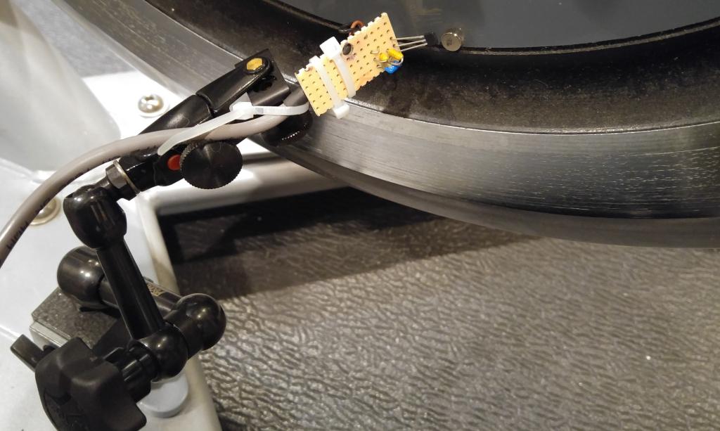
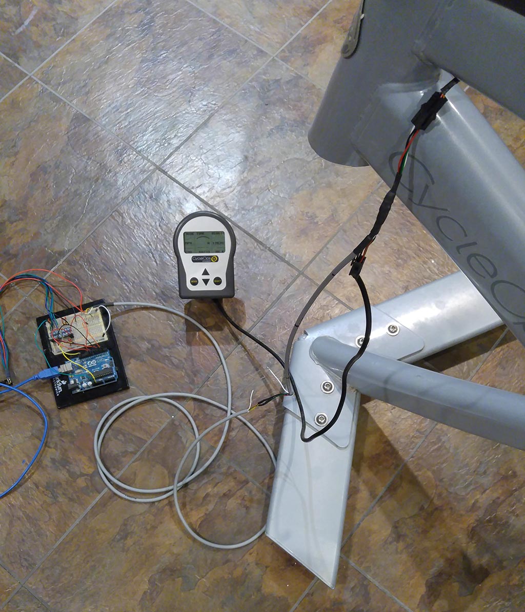
Wheel Speed
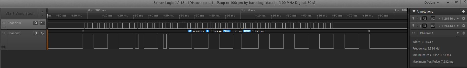
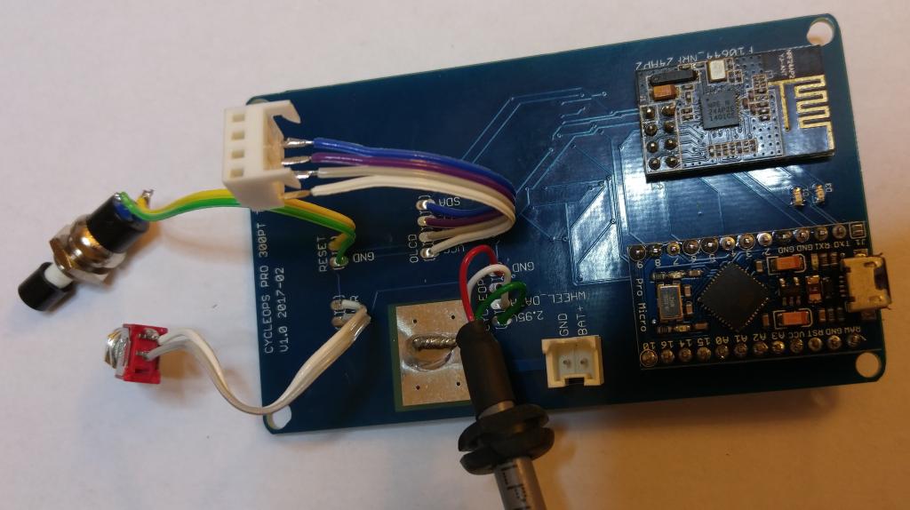
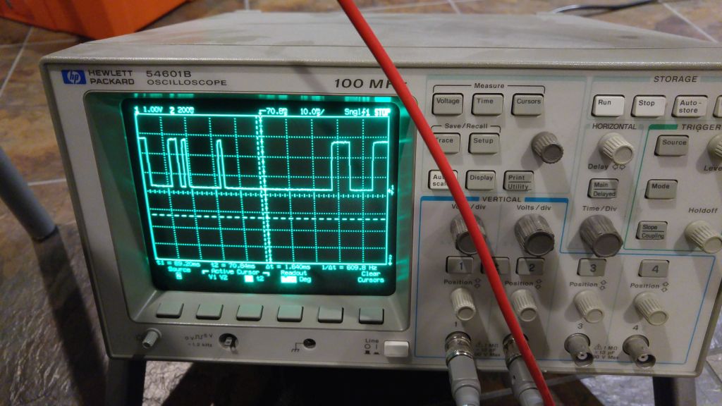
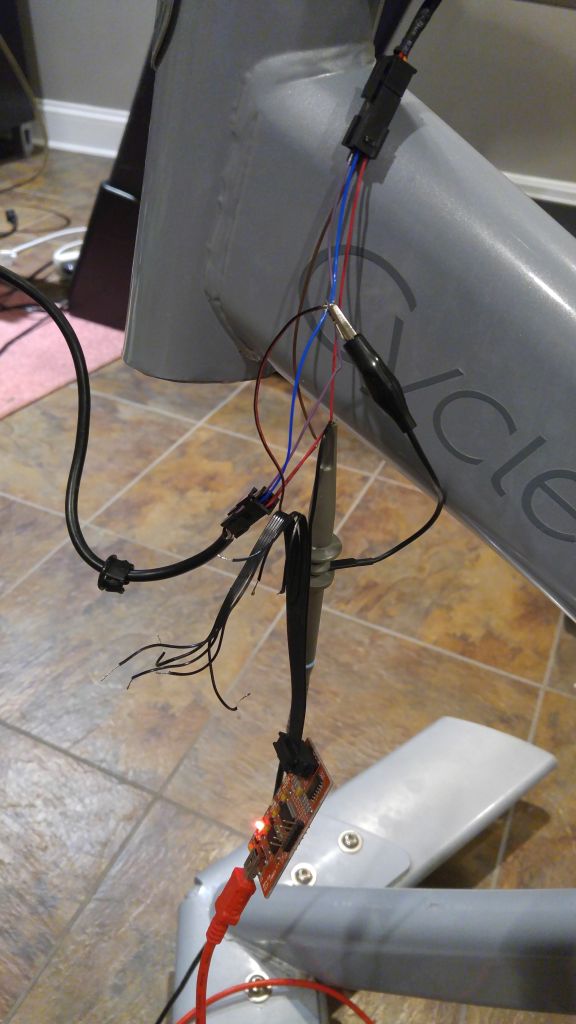
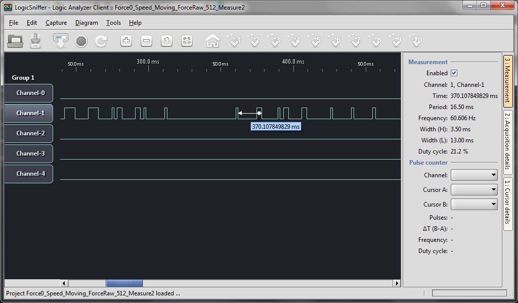
Once I had a stable output of the wheel speed part of the data steam I knew I needed a way to relate it back to “real” flywheel speed. The simplest approach I came up with was to build a quick hall effect sensor circuit to measure as a small neodymium magnet stuck onto the flywheel passed by. The flywheel is a solid chuck of steel so attaching the magnet was super easy, just let it hold itself on. I still haven’t gotten it off, but it’s not hurting anything. I wrote some code to output the raw data steam (Torque and Wheel Speed) from the CycleOps bike along with the time between each wheel rotation. Plotting these against each other provided a vary satisfying straight line
For speeds of zero the hub will output 4095 counts. Otherwise the wheel_period in µsec can be calculated by
WHEEL_SLOPE = 527.2213800;
WHEEL_OFFSET = -3181.8199961;
wheel_period = wheel_speed*WHEEL_SLOPE+WHEEL_OFFSET;
This would give a wheel speed of 27.8 RPM or a cadence of 7.49 RPM. Since no biker is riding along at 7.49 RPM it seems perfectly fair to call any speed slower 0.
From this we can convert to rad/sec by
omega = 6283185.30718/wheel_period;
Back to the cadence number, since this bike is essentially a fixed gear bike if we know the rear hub (flywheel) speed we can also know the pedal cadence by dividing by the gear ratio. Hence from above 27.8 RPM (flywheel) * (14/52) = 7.48 RPM cadence. This feature of the bike was very nice as it allowed me to easily output cadence over ANT+. One of the metrics I really like to log along with power.