I’ve received a few requests for a step by step tutorial on how to build the circuit that I had talked about below. Sorry, this post won’t be that step by step guide but it will provide many of the tools. As a mid stop on my way to making a robust design others can copy I built a battery powered, hand wired, point to point monster that I could keep connected to the bike for my own personal winter training. At the same time I drew up the electrical schematic and laid out a PCB that would make it easy for others to build at home without doing painful point to point wiring. I had a few requirements for the finial design.
- Li-Ion Battery Powered
- Built in USB Charger for the battery
- Built in display to show, Torque, Power, Cadence and some parameters for debugging such as the current torque zero offset
- USB programmable for firmware updates and general messing with it at a later time without needing to use an In-Circuit Serial Programming (ICSP).
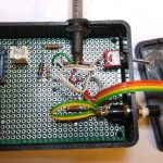
Battery: I’ve have a pile of 14500, 900mAh 3.7V Li-ion batteries laying around that fit perfectly in the corner of the project box. I’ve been using the bike about an hour a day for the last month and have yet to need to charge it. One of these days I’ll measure the power draw to get a rough idea of how long it should last. This first prototype has no ability to charge the battery. I’ll have to use one of my external chargers to do it for now
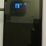
Display: I chose to use a small 128×64 OLED display that I had been playing around with. It has incredible view-ability, draws very little power and will run off 3.3V without any external components. It also has really easy to use libraries that made getting the data on the screen very quick to add to the code.
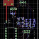
The hand wired unit I built does not have a built in charger but that is addressed in the final PCB design.
Just as before, the PCB design files and source code can be found in Github CycleOpsPro300PTtoANTPlus. SeeedStudio the PCB vendor I used has a minimum 5 board order so if there is any interest leave a comment below and I’m happy to send the extra to a good home $5 a board.
For anything following along at home the ANT+ module I had previously used doesn’t look to be available anymore. I found one that looks to be exactly the same NRF24AP2 Networking Module / 8-channel / Serial Interface / ANT Networking. This will be the unit I test with the PCB version of the design.
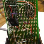
Photos of of the hand wired box and the PCB layout


